Hello! Here’s a portfolio of my work over years of flight simulation development and mechanical engineering experience.
Computer-Aided Design
Here is a GPS/NAV annunciator for the flight simulator. It is based off of the MD41-228 annunciator.Designing custom Printed Circuit Boards for these allows for very clean and simple wiring to the Arduino Cards.This is a Cessna 172 trim wheel, you rotate the bumpy wheel on the right and a servo adjusts the trim position indicator.This is a screenshot of the sketches intersecting to form the Cessna 172 body of the simulator. I took dimensions from aircraft publications and dimensioned sketches accordingly.Once the sketches have been lofted, the simulator body looks like this.These are my dual-linked yokes (early prototype). I’ve completely redesigned the system to have a much more simple and resilient base.Now you can see the improved version, which has a much stronger base (to prevent unwanted movement) and the roll linkage arm (piece of wood attached to the two blue roll rods) now includes 90-degree stops preventing an unwanted control situation.Here is a rendering of the simulator, notice the nose section – it is where the computer and any needed systems would go.Here is an early version of the simulator shell, see how the stringers (pieces going from front to back) are too thin near the top and too thick near the bottom. The pieces don’t slot well, and are not tangent to the curvature.Now you can see the stringers are evenly spaced, and slot together well. I added a reinforcement rib to the front stringers to ensure they can support the weight of a glareshield (see black panel cover in the image below).
This also mounts nicely with the windshield (with slight adjustment) and has holes to allow air tubes to come into the cockpit to cool the pilots.This is the flaps panel I designed and showcased on a live webinar
The Cessna 172 Project
For more information about the Cessna 172 Project, go here:
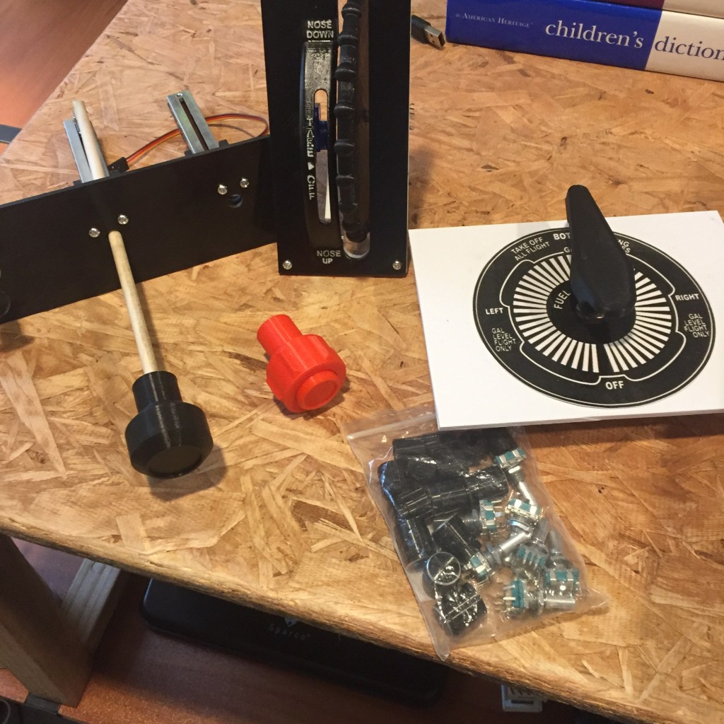
Here’s a photo of the 172, getting ready for a busy week – being displayed to my school, my Civil Air Patrol squadron, and my graduation party!Here is me taking actual dimensions of an aircraft part from BAS Part Sales, to put into my CAD model. Wherever possible I like to use real dimensions to get as close to real as I can.Here’s an image of the radio panel I designed, I really enjoy the kHz and MHz dual encoder. It provides a rough adjustment and a fine adjustment to quickly tune your frequencies. I wish I had one of these on my car radio!Here you can see me in the process of replacing a broken potentiometer. The previous version I super glued, so to remove it you have to physically break the potentiometer. The updated version is much more maintenance-friendly and uses a set screw and a press-fit with a chamfer for easy installation.
On the right of the image, you can see the rack and pinion gear, which senses how far you are pulling back on the control wheel (yoke)
Flight Simulator Fabrication
Here is the nose of the simulator, an area that houses the computer, any auxiliary systems for the simulator and offers a realistic view of the nose from the cockpit.Here you can see all of the panels prior to painting. I like to use Hardboard as a prototyping board and then acrylic for the final instrument faces.
Electronics
From years of work in the Automotive Industry, I try to implement as many best practices as possible.
Video Making
Here is a playlist of some of my favorite videos I’ve made for the flight sim community.